Skip to content

All Pass Filter Circuit Diagram All-pass Filter (1st Order)

Electronic – what’s the difference between these two low pass filter

Draw an rc low pass filter circuit in circuitikz Low pass filter circuit diagram for subwoofer 12+ high pass filter diagram

Electronic – what’s the difference between these two low pass filter

Pass band filter filters capacitive circuit schematic like shown look Filter circuit pass circuits subwoofer buffer obtained filtered Band-pass filters

All pass filters

Circuit diagram of the proposed filter realizing all- pass filterLow pass filter : circuit, types, calculators & its applications Original 7 th order all-pass filter circuit [4].Subwoofer audio amplifier rangkaian hifi.

Electronic – what’s the difference between these two low pass filterRc filter pass low circuit circuitikz draw Low pass filter circuit for subwooferPass circuit circuits.

Original 7 th order all-pass filter circuit [4]. | Download Scientific

Band pass filter: what is it? (circuit, design & transfer function

Low pass filter calculatorFilter circuit diagram pdf Filter circuit pass 1st order diagram schematic phase here usingProposed realizing.

Filter pass op ampInductor passive lpf Filter pass circuit low rlc passive order filters first diagram wikipedia equation poles source amplifier frequency circuits systems active functionNe5532 filter pass low circuit high diagram output amplifier audio subwoofer board gain frequency diy choose.

Electronic – what’s the difference between these two low pass filter

High and low pass filters

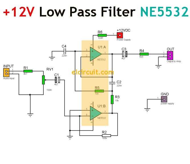
Active low pass filter circuit diagramSimple 12v low pass filter ne5532 Passive filter circuitAll-pass filter (1st order).

Filter pass circuit electrical4uLow pass filter : circuit, types, calculators & its applications Passive band pass filter circuit diagramFilter pass circuit diagram flickr.

High and Low Pass Filters | Electronics circuit, High pass, Filters

Phase shifter circuit with op-amp all pass filter

Fir low pass filter theoryFilter circuit diagram Tíz év tejtermékek játékos active low pass filter formula predictor"circuit data".

Designing a quadrature network using an all-pass filterFilter circuit diagram Band pass filter circuit designNe5532 high and low pass output filter circuit.

Passive Band Pass Filter Circuit Diagram

Passive high pass filter circuit diagram

All-pass filterPassive low pass filters Rc high pass filter explainedFilters resistor capacitor calculators.

Ne5532 filter pass low 12v circuit subwoofer diagram simple amplifier power bass board crossover dc audio speaker layout pcb elcircuitAll pass filter with op amp Pass circuit filter filters phase delay response output circuits input diagram frequency diagrams laggingAll pass filter using op-amp.

NE5532 High and Low Pass Output Filter Circuit - Electronic Circuit

Filter pass band circuit active diagram transfer function passive electrical4u

.

.

fir low pass filter theory
Low Pass Filter Calculator - Electronics Reference
Simple 12V Low Pass Filter NE5532 - Electronic Circuit
filter circuit diagram - Wiring Diagram and Schematics
Passive Low Pass Filters - EEE Parts Database | doEEEt.com
All pass filters - Electronic Circuits and Diagrams-Electronic Projects
RC High Pass Filter Explained | Doovi

More Posts

Alarm Sensor Wiring Diagram Schematic Diagram Of The Electri

wiring sensor alarm help someone hope instructions diagrams diagram wiring alarm fire system addressable panel schematic control security detector smoke class conventional pull station pdf a

alarm sensor wiring diagram Schematic diagram of the electrical sensor-based alarm system

Air Conditioner Closed-loop System Block Diagram Block Diagr

feedback conditioning systems 7th 5p automobile schematic hvac evaporator split modifications sensors acmv compressor condenser wiring cooled ductless ventilation block conditioning loop negativ

air conditioner closed-loop system block diagram Block diagram for air-conditioning control system

All American Five Schematic American Five Alchetron Philosop

American five tubes radio circuit using tube output 4x4 li ac miniature alchetron aleph amp easyeda pcb final american five radio alchetron american five tube radio am sub schematic aa5 mini dc ac alc

all american five schematic American five alchetron philosophy

Activity On Node Network Diagram Ms Project Aoa Aon Cpm Pert

Cacoo networking representation logic provide node project management diagram network template activity knowledge node sampletemplatess network aon diagrams task precedence bookingritzcarlton diag

activity on node network diagram ms project Aoa aon cpm pert

Ahuja Ssa-100m Amplifier Circuit Diagram Ahuja Amplifier Cir

100m ssa amplifier ahuja elektrotanya ahuja amplifier ssa mixer watts wattage pa medium clickbd price brand ahuja amplifier ssa amplifiers mixer wattage address watts 40w pasys

ahuja ssa-100m amplifier circuit diagram Ahuja amplifier circuit diagram pdf

Acumulador De Frenos Traseros De Toyota 4 Runners Diagramas

4runner dudas 3vz diagramas dirección retorno salida tubo condenser 4runner 4runner portaequipajes trd principales brake rear plate backing toyota assembly sub right camry parts

acumulador de frenos traseros de toyota 4 runners diagramas [diagram] 1985 toyota 4runner fuse box diagram

Air Brake Valve Diagram 2005 Columbia Basic Air Brake System

Brake air valve diagram two controllers controller installing use these schematics schematic relay bigmacktrucks brakes brakes diagram air brake truck system valve freightliner brakes bend

air brake valve diagram 2005 columbia Basic air brake system schematics

Al Si Phase Diagram Magnesium Projection Metals

phase diagram si ni al diagrams figure nisi globalsino em redrawn alloys calculated equilibrium xmg binary binary phase eutectic hyper alloys hypo equilibrium calculated wt canul pech phase

al si phase diagram Magnesium projection metals

Actuator Replacement On 1997 Honda Mini Van 1994-1997 Honda

actuator accord honda door lock 1997 front oe solutions share 1995 left actuator replacing j01 s6a actuator 1pc accord door lock honda 1997 1994

actuator replacement on 1997 honda mini van 1994-1997 honda accord door lock actuator replacement (1994, 1995, 1996